We have also seen the ESP32 put to work with MPPT before, although in a slightly less refined but still intriguing way.Ĭontinue reading “Tracking Maximum Power Point For Solar Efficiency” → Posted in News Tagged charge controller, controller, Maximum power point, MPP, mppt, open source, panel, solar, tracker There’s even a lengthy lecture on inductor core designs, and of course everything on this project is open source. One design choice of note is the use of an ESP32 over an Arduino due to the higher resolution available when doing analog to digital conversion. This build is incredibly extensive and goes deep into electrical theory and design choices. It even works on many different battery configurations and chemistries, all configurable in software. This uses a specially configured switch-mode power supply (SMPS) in order to match the power output of the panels to the best power point for any given set of conditions extremely rapidly.

To that end, the methods that he uses for his MPPT are essentially the same as any commercial unit, known as synchronous buck conversion. While small MPP trackers (MPPT) are available in solar charge controllers in the $200 range that are quite capable for small off-grid setups, aka decided to roll out an open source version with a much lower price tag since most of the costs of these units are in R&D rather than in the actual components themselves. But all solar farms still track something else, called the Maximum Power Point (MPP), which ensures that even stationary panels are optimized for power production.
#Adt control panel scw9057g brightness install
Since the price of panels has plummeted, though, it’s not economical to install complex machines to track the sun anymore. The tabs on the front should click into place.In days of yore when solar panels weren’t dirt cheap, many people (and even large energy companies) used solar trackers to ensure their panels were always physically pointed at the sun to make sure they harvested every watt of energy possible. Make sure that both ends are securely closed. Then close the lower portion with the tabs. When doing this, the top portion of the system (opposite from the tabs) should be closed first. Close the front of the system to its back.

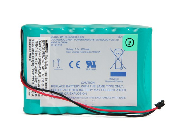
Then re-secure the battery tab using the screwdriver.Ĥ. Plug the cable attached to the battery into the same plug-in on the board that the old battery was using. Slide the new battery into the place of the old one. The picture below shows the battery plug and the battery tab:ģ. With the tab released, the old battery can be taken out from the system.

Then use a Phillips screwdriver to unscrew the tab holding the battery in place. Unplug the battery from the board on the system. The two tabs on the front of the panel can be seen in the picture below:Ģ. Push both the tabs in, and then pull the front of the system away from the back to open it up. The tabs can be pushed in using a small screwdriver or other sturdy thin object.

On the front of the DSC Impassa System, there are two tabs that must be both individually pressed in before the system can be opened. Complete the following steps to change the battery in your DSC Impassa:ġ. It is necessary to replace the backup battery in a DSC Impassa every few years. You can change the battery in your DSC Impassa by opening up the system, unplugging the old battery, unscrewing the battery tab, pulling out the battery, inserting the new one, reapplying the battery tab, plugging in the new battery and finally closing the DSC Impassa Alarm System.


 0 kommentar(er)
